Vinicio Coletti
Electronic dice
Click the picture to see a movie
Clicca qui per questa pagina in lingua italiana
Description
Some friends asked me to do an electronic dice, just for fun. I thought this was the
occasion to write a simple yet interesting program for the usual PIC 16F84 chip.
Thus I wrote such a program and decided to publish the entire project, including
the assembler source, for educational purposes.
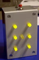
The dice will simply show a random number, 1 to 6, using 7 leds put in the same
shape as the dots on a dice faces. When the user push a button, a new random number
is generated and shown. After about ten seconds of inactivity the leds are switched off,
to save the battery.
Since in this application the timing is not critical, we can save the crystal and
run the chip on the internal RC oscillator. The frequency of oscillation will depends
on the resistor and capacitor used, as well as the voltage and the ambient temperature.
At 25° and the rated 4.5 V, the clock in this circuit will be about 620 kHz,
giving an istruction rate of 155 kHz (6.45 µs per istruction).
Port A of the chip will not be used at all, while the first pin of port B (RB0/INT)
will be used to connect a push button, normally open.
The other seven pins of port B (RB1 - RB7) will drive the seven leds.
The power to the circuit will be given by 3xAA cells, so 4.5 V, but you can try
also with three or four NiMH rechargable cells (3.6 - 4.8 V).
The clock will change depending on the voltage used: the higher the voltage, the slower
the clock. This will only change slightly the timeout used to switch off the leds, all other features
being exactly the same.
The dice circuit

The components list
- 1 Microchip PIC 16(L)F84(A), in the 18 pins PDIP package
- 7 standard leds, of any color and size you like (max 20 mA current)
- 7 resistors of 150 Ω ¼ W
- 1 resistor of 10 kΩ ¼ W
- 1 capacitor of 100 pF 15 VL
- 1 pushbutton, normally open
- 1 switch
- 1 battery holder for 3 AA cells
- 1 box to contain the circuit and the batteries and, on the outside, leds, switch and button
The program
The are several ways to generate a random number to simulate the rolling of a dice.
I simply make the main program increment a variable at the maximum possibile speed. This infinte
loop requires 3 istruction cycles for every increment, thus we will have about 52,000 increments
per second. When we push the button, we generate an interrupt and the interrupt service routine
will read the current counter value and will use it to generate a random number in the range 0
to 5. This number will be shown by the leds as a number in the range 1 to 6.
To generate the random number, the program will look at the 3 least significant bits of the
counter (value 0 to 7). If we have an invalid value (6 or 7), the program will look at the 3 bits
on the left and if we have another invalid value, another byte is used. So the tmr0 register
is taken (it is the timer counter) and here also we look for the 3 least significat bits and
then, if needed, to the 3 immediately on their left.
A wrong generation has thus a probability of about 0.4% and in
this case we will simply need to push again the button to have a valid number.
Of course we could make a better algorythm, but I think this is good enough for an aducational
project and beware of the counters manipulations, because it is very easy to obtain
a not uniform distribution of the six numbers!
To signal a wrong generation, I make the seven leds blink all at the same time.
Another problem, very secondary however, is that pushbuttons tend to give many pulses when
we press them once, until the mechanical parts stabilize. One can decide to simply let
the button give all these pulses, so that many random generations would occur within a
few milliseconds (only the last stable one will be visibile on the leds) but I decided
to provide a protection for this: when we press the button, all subsequent pulses
are disabled for about 300 ms.
Since there are three different operations linked to time passing (blinking the leds,
re-enabling the button and switching off the leds), we need that also
Timer 0 generate an interrupt. This timing interrupt will increment a second counter,
used to know when we have to do the different operations.
Thus, basically the whole program is contained in the interrupt service routine, called
either by a button pressure or by a timeout of Timer 0.
You can find further details on the assembler code, that I commented heavily for
educational purpose. I think it is possibile to learn a lot of things about PICs
from this simple code.
The Assembler source code
What follows is the commented source code for the dice program (dice.asm).
You can compile it with the freeware suite MPLAB that you can download
from the Microchip site.
; DICE.ASM - Electronic dice with a PIC16F74(A) and 7 leds - (c) Vinicio Coletti 2005
; First of all we must inform the assembler program and the development environment
; about what chip we are using in this source
	LIST	P=16F84A
; then we load an include file with many symbolic definitions that simplify
; the writing of the program; for example if we want to stop all interrupts
; we must clear the most significant bit in the interrupt control register
; writing: bcf 11,7 which is quite obscure, whilst using the mnemonic
; definitions we could write: bcf INTCON,GIE that is easier to understand
	INCLUDE	<p16f84a.inc>
; the other important thing to do initially is to define the bits
; of the configuration word, which are stored on the chip in the
; programming phase and are not accessible by the program;
; here we say: the power on delay is ON, code protect is OFF,
; watchdog timer is OFF, the oscillator we use is RC
	__CONFIG _PWRTE_ON & _CP_OFF & _WDT_OFF & _RC_OSC
; now this is somewhat optional: we say we want to be informed of all errors
; during compile (this is a message to the compiler)
	ERRORLEVEL 1
; another information to the compiler: the numbers we write in the source
; are to be considered in decimal notation, if not otherways stated
	RADIX	DEC

; now we begin to define the variables used by the program
; the user RAM bank in the 16f84(a) begins at address 0x0c and
; ends at address 0x4f for a total of 68 bytes
; we define several variables, all of 1 byte each (the default)
; simply listing their names; the first will be at address 0x0c
; the second at 0x0d and so on; we need only seven bytes!
	cblock	0x0c
	count				; counter used to generate the random number
	flag				; contains several 1 bit flags
	nint				; timer interrupts counter, each unit about 82 ms
	save_w			; save w register during interrupts
	save_status		; save status register during interrupts
	num				; stores the generated random number 0-5
	try				; counter of the generation tries
	endc

; we need two different 1 bit flags and to simplify their access
; we define two symbolic names for them
#define	f_ledon	flag,0	; it is 1 if leds are ON
#define	f_blink	flag,1	; it is 1 if leds must blink

; at this point we can begin to write the real program istructions!
; but first we need to say to the compiler which is the address
; of the first istruction; it will be ZERO because on power on
; reset, the program counter is set to 0; this is the start of all
; PIC programs
	org	0
; now lets begin the program; we can put here only 4 istructions
; at addresses 0,1,2,3 because at address 4 there is the interrupt vector!
; we begin by clearing the register of timer0 and the two i/o ports
; this is not mandatory, but I like it :-)
	clrf	TMR0
	clrf	PORTA
	clrf	PORTB
; then we must jump over the interrupt vector and continue
; to main program
	goto	begin
; this is the interrupt vector! whenever an interrupt occurs,
; the program counter is loaded with the address 4, so the
; program execution jumps here; I put a goto to the real
; interrupt service routine
	goto	inter
; here there is the continuation of the main program
; first of all we must configure some important
; registers and we begin with the i/o ports
; since the special registers TRISA and TRISB are in the high bank of RAM
; we need first to set the bit RP0 in the STATUS register
begin
   bsf	STATUS,RP0
; in every port definition 0=output pin and 1=input pin
; port A is not used and set to all inputs
	movlw	0xff
	movwf	TRISA
; port B is all outputs, except the first pin, used for the button
	movlw	1
	movwf	TRISB
; now we set the OPTION register, where each bit sets a different feature:
; - internal pull-up resitors on port B are enabled
; - external interrupt in on falling edge (1 to 0 transition)
; - istruction clock is from internal oscillator
; - prescaler is assigned to timer 0
; - prescaler value is 64 (1 timeout every about 105 ms)
; for clarity the value is specified in binary notation
	movlw	B'00000101'
	movwf	OPTION_REG
; now we go back to bank 0 of RAM, where we have our variables
	bcf	STATUS,RP0
; we clear (that is set to 0) some variables, as needed
	clrf	count
	clrf	flag
	clrf	nint
; now we enable the interrupts, setting three bits in the INTCON register
; they are the external interrupt enable (INTE), the timer 0 interrupt
; enable (T0IE) and the general interrupt enable (GIE)
; to be shorter we do it loading a single value in INTCON
	movlw	B'10110000'
	movwf	INTCON
; now we are finished with the initialitazion and we can begin the
; main program, which in this case consists simply in an infinite
; loop where the variable count in incremented 0 to 255 and then
; it rolls back to 0 and so on ad libitum...
; the value of count will be used to generate the random numbers
; and all the processing will happen in the interrupt service routine
loop
   incf	count,f
	goto	loop
; here is the interrupt service routine! all things will happen here
; first of all we MUST save the current STATUS and W registers
; the istruction MOVF must be avoided, because in alters the status!
inter
   movwf save_w
	swapf STATUS,W
	movwf save_status
; since there are two possibile interupt source in this program,
; first of all we must know who generated this interrupt;
; if it was not the timer, we jump to the button routine
   btfss	INTCON,T0IF
	goto	intbutt
; if we are here, it's not the button, so it's the timer
; first of all we increment the number-of-interrupts variable
	incf	nint,f
; then we clear the timer interrupt flag, to enable it for the next time
	bcf	INTCON,T0IF
; now we should know what we have to do: enabling the button?
; switching off the leds? blinking them? but if the leds are
; already switched off, we must do nothing and exit the routine
; this state is signaled by the f_ledon flag
	btfss	f_ledon
	goto	endint
; here the leds are ON so we should see if the button is already enabled
	btfsc	INTCON,INTE
	goto	int1
; here the button is disabled, so we check if about 300 ms are passed
; from the last random number extraction, that is 3 timer interrupts
	movlw	3
	subwf	nint,w
; if the time passed is shorter, we don't enable the button and
; jump also the led switching routine, that will happen later
	bnc   int2
; here about 300 ms are passed, so we re-enable the button, if released
   btfss PORTB,0
	goto	int1
	bcf	INTCON,INTF
	bsf	INTCON,INTE
; either button was already enabled or it was enabled now, here we are!
; where we check if about 10 seconds are passed, to switch off leds
int1
   movlw	100
	subwf	nint,w
; if less than 10 seconds, we jump to the next routine
	bnc   int2
; otherwise we clear all port B, where leds are connected
; and we clear also f_ledon to remember that leds are now off
	clrf	PORTB
	bcf	f_ledon
; since we have switched off the leds, they must not blink either
; so we jump directly to the end of the interrupt routine
	goto	endint
; if time was shorter than 10 seconds we arrive here to see
; if leds are in a blinking state, if not we jump to the end
int2
   btfss	f_blink
	goto	endint
; here we must blink the leds; we do so linking the state of bit
; number 1 in the number-of-interrupts variable to the state of
; the leds (1=on 0=off); since this bit changes every 2
; Timer0 interrupts, this will produce about 210 ms withs leds ON
; then about 210 ms with leds OFF (about 2.4 blinks per second)
	btfsc	nint,1
	goto	blinkon
	clrf	PORTB
	goto	endint
blinkon
   movlw	B'11111110'
	movwf	PORTB
	goto	endint
; here we arrive if the interrupt was generated by a button pressure
; first of all we disable further button interrupts
; they will be re-enabled by the timer about 300 ms later
intbutt
   bcf	INTCON,INTE
; then we clear the counter of timer interrupts,
; this is zero time for us!
	clrf	nint
; we set the flag telling that leds are on (either normal or blinking)
	bsf	f_ledon
; we initialize a variable to make 2 tries of random number generation
	movlw	2
	movwf	try
; this is the generation loop,
; we look at the 3 least significant bits of count
gen
   movlw	7
	andwf	count,w
	movwf	num
; if the number is less than 6, it's all ok
	movlw	6
	subwf	num,w
	bnc   ok
; if not, we try shifting count 3 bits to the right
	rrf	count,f
	rrf	count,f
	rrf	count,f
; than we get the 3 least significant bits again
	movlw	7
	andwf	count,w
	movwf	num
	movlw	6
	subwf	num,w
	bnc   ok
; here we are still with a wrong number, so we make a second try
; getting Timer0 counter value, from TMR0 register
; to repeat the try, we put it inside count variable
	movf	TMR0,w
	movwf	count
; we decrement the try variable, first time it will be different
; from zero, so we will go on to the "goto" that brings us back
; to the generation routine; the second time the goto will be jumped
	decfsz   try
	goto	gen
; here both generations failed, so we set the led blink flag
; then we exit the routine; the timer will blink all leds
	bsf	f_blink
	goto	endint
; here the random number is OK, in the range 0 to 5, we reset blink flag
ok
   bcf	f_blink
; then we get the generated number and decode it for output
	movf	num,w
	call	decod
	movwf	PORTB
; clear the counter, to avoid correlation with tmr0 value
	clrf	count
; this is the common end for the two interrupt routines
; we restore the STATUS and W registers, then we exit interrupt routine
endint
	swapf	save_status,w
	movwf	STATUS
	swapf	save_w,f
	swapf	save_w,w
	retfie

; this routine decodes the random number 0-5 to the value needed to
; switch on the seven output leds as if they were on the face of a dice
; these values depend on the circuit wiring;
; to decode, we will add the input value in W to the program counter PCL
; in fact, this is a computed-goto
; the "dt" generates a "retlw" istruction, which is a "return"
; loading also a value into the W register; so we simply list
; the six needed values and the routine will return with the selected
; one loaded in the W register
; please note that in longer programs, where a table routine like this
; is placed in a different 256-bytes-page than the rest of the program,
; it would require at the beginning the correct setting of
; PCLATH register
decod
   addwf	PCL,f
	dt    B'00010000'
	dt    B'00101000'
	dt    B'10010010'
	dt    B'10101010'
	dt    B'10111010'
	dt    B'11101110'
; and finally we must tell the compiler that the source code ends here
	end

; and this is the end of the source code of DICE.ASM
; by Vinicio Coletti (c) 2005	- 2015