Vinicio Coletti site
R/C Boat
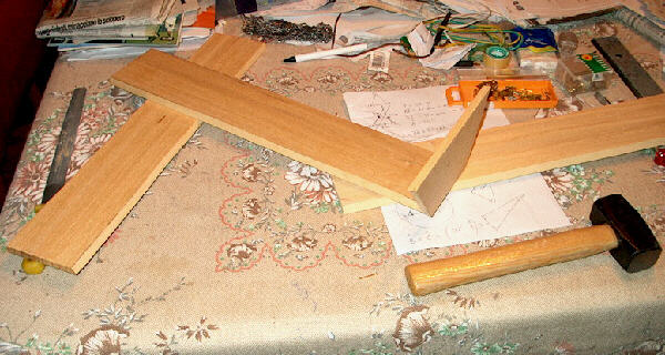 |
Here is the beginning of the story. In November 2001 I went to a big hardware store and bought five cheap pieces of wood. I don't even know what kind of wood it is, but it's quite light. Each table is 50x10x1 cm. |
| Three tables were only cut a bit along one border, to put them at the right inclination. I derived from the other two tables the rear trapeze and the three triangles for the front. | 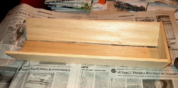 |
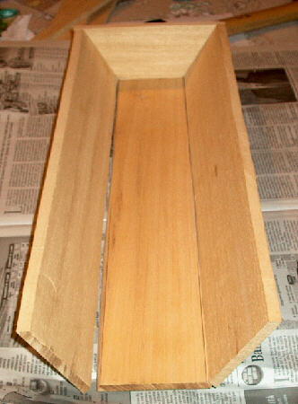 |
To build the boat vessel I didn't use any metal parts, but only a good two-components glue, specific for wood. You may argue that the vessel is not too idrodynamic, but, well, this boat was not designed thinking to speed. |
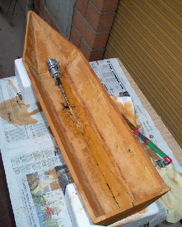
| I installed then, after some months I left it apart, a 600BB cc motor, with joint and propeller axis. The inclination of the axis is about 10 degrees and the propeller is plastic and it has a diameter of 4 cm. | 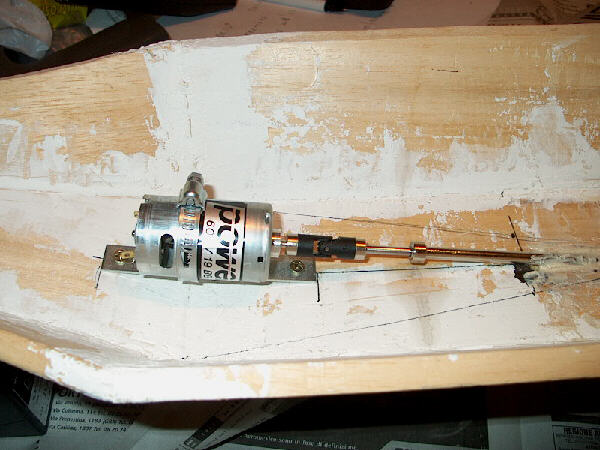 |
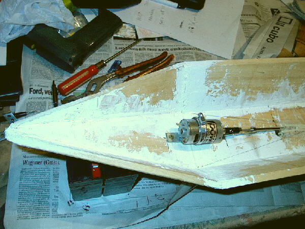 |
This is another view of the electric motor and the frontal part of the boat. |
| This is a bottom view of the propeller and the axis. Since the 600BB motor is directly connected to
the propeller axis, it must rotate quite quickly, thus I choosed a two-blades propeller. I am not sure
this reasonment is correct... The inner motor axis rotate inside an outer metallic pipe, which is fixed to the boat shell. Between the two metallic parts I put some drops of mineral oil. |
 |
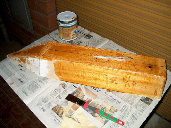 |
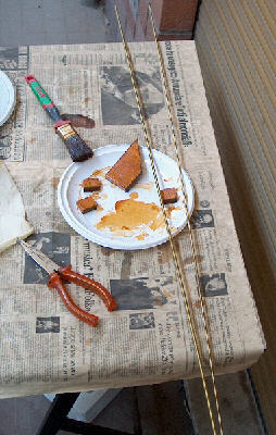
In June 2002 I realized that if I wouldn't work at the boat, it will not sail during summer holidays, so I bought the colors and I begun painting. |
| The first kind of paint colors the wood, so that it looks much better, and protects it against the infiltration of water. I put three layers of this painting on the boat. | 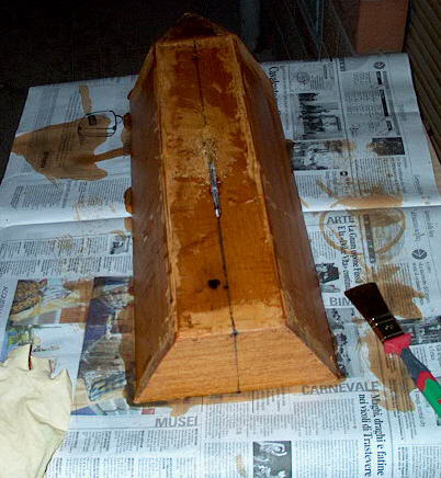 |
 |
The second paint is named flatting and is a water repellent. I put two layers of it on the boat. |
| At the end I tested the boat in my bathroom, just to see if it really didn't sink... It was ok! I estimated a volume of about 5 dm3, so the weight of the boat must never go over 5 kg. Actually, to have a good navigation, I decided not to go over 2,5 kg, all included. |
 |
 |
In July there was still a lot of work to do: I had to make and install the rudder and also make the controller card for the motor, because I decided not to buy a commercial controller. I cut the rudder from the same wood used from the vessel and painted it the same way. A metallic bar and pipe made the rudder axis and I cut them to the right length. |
| Here is an external view of the rudder. To drive it I used the servo I found included in the Futaba R/C transmitter package. Unfortunately, during one of the tests of the motor controller I inverted the power cables and the servo burned in a second. I had to buy another one. The controller survived, because I put a protection diode on it. | 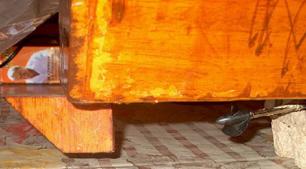 |
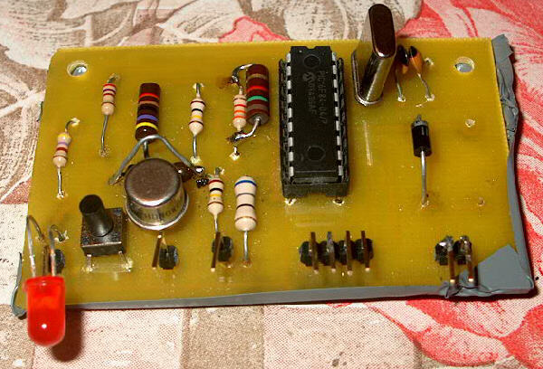 |
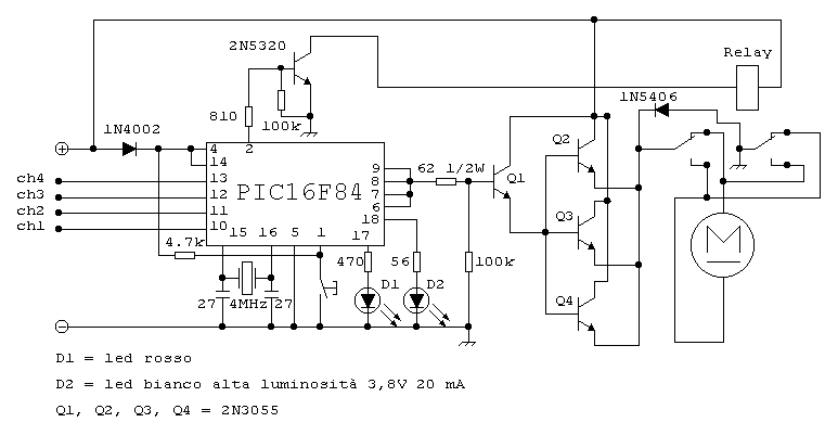
This is the motor speed controller card. It is on a pcb and is based on the Microchip PIC16F84A microcontroller and few other components. Look here for a detailed description of the card. |
| This is the rear part of the boat. You can the the lead acid battery (6 V, 4 Ah), the rudder bar, the servo, the R/C receiver (Futaba, 5 channels, 40 MHz) and the motor controller card. | 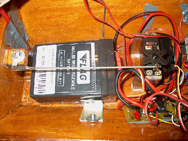 |
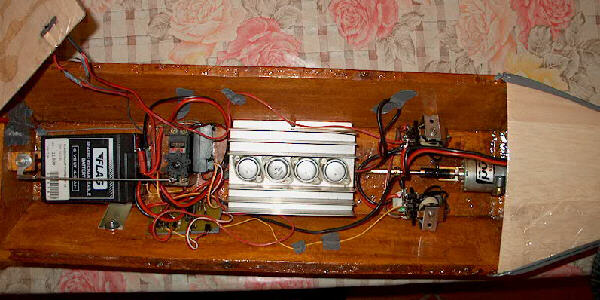
| Here we see the power transistor module (4 x 2N3055 on a dissipating module). They are connected in a Darlington configuration, with the first one driving the other three in parallel. This permits a steady motor current of about 15 A or more and peaks of 45 A (about 270 Watt). | |
| Here you can see the motor and the two relays. I wanted to use a single 30 A x 2 relay but I found only these one, that are 10 A x 3. So I put two of them, with the three switches put in parallel. They are used to invert the motion direction, forward or reverse. Although the reverse is barely used, it can be vital in some situations (and is also a good brake). | 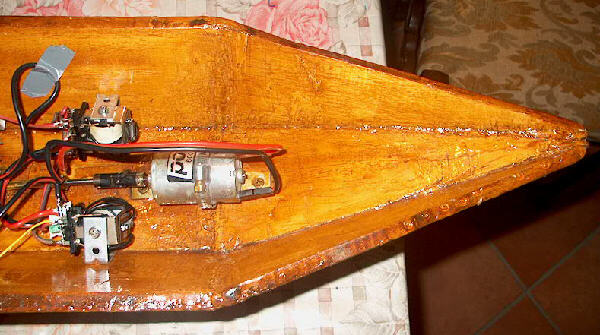 |
 |
Here is a total view of the boat, with all components and ready to go. The coverage is made with balsa wood packed with oven paper. It is a temporary solution, because I think I will paint the balsa the same color of the boat. |
| The boat is now really ready to go! On the left side you can see the Futaba R/C transmitter. The antenna is made with the wire of the receiver put inside several plastic pipes (those used for drinks!). Light and cheap. The coverage was put in case some water enters the boat, but of course has the problem to reduce the dissipation of the heat coming from the motor and the transistors module. Some other solutions may be tried in the future. | 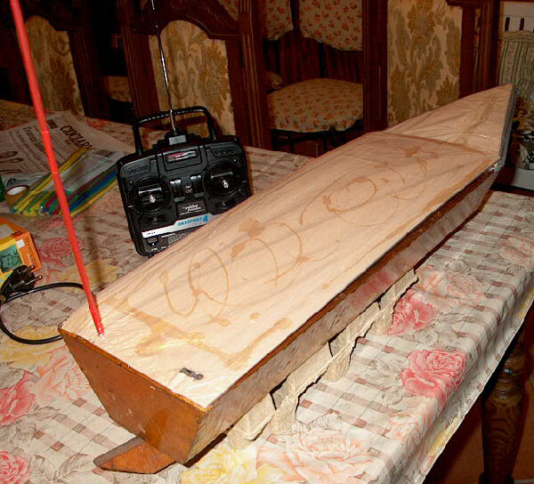 |
 |
Here is the boat sailing at a very slow speed in a lake, not too far from the shore. Here ther antenna is a yellow pipe :-) The first time the speed was actually limited because the motor axis was not fixed well to the motor. Tightening some screws fixed the problem. |
The motor control circuit
Released August 10, 2002
General descriptionThis controller is part of the homebrew remote controlled ship I built during summer 2002. Power and featuresThe controller card gets its power from the 6V lead accumulator that powers all the ship. Actually,
the voltage goes up to about 6.7 V for a full charged battery, so a series diode protects the PIC from voltage
inversions and drops the voltage by about 0.7 V. The PIC 16F84A should not receive more than 5.5 V
but I found that even at 6.0 V there is no problems, so the single diode is the unique regulation
of the input voltage.
Reading the pulsesThe main purpose of the program on the PIC is to read the R/C pulses coming from the radio receiver, compute
the desired speed and produce adequate pwm pulses on the output, thus regulating motor's speed.
Thus a whole sequence lasts at most 17 ms and if the trasmitter doesn't pause itself, you can have more than
59 motion commands per second. It's enough even for very fast airplane models, I guess. How it worksWhen a TTL input goes up, a PORTB interrupt on change is generated. The interrupt service routine
reads and saves the current Timer0 value, for future use. When the TTL input goes down, another
interrupt is generated and this time the service routine computes the difference with the saved value,
stores it and activates a validity flag. The bugThe very first version of the program had a serious bug: there was no total OFF of the motor when
the paddle was in the center position and there were always spurious max speed pulses. Debugging
was useless, until I went back to the Microchip manuals to read carefully how the "PORT B interrupt
on change" really worked. This way I discovered that when I switched ON or OFF the pwm output
(four PORT B pins), I fired at the same time the interrupt, because every write to a port is also a
read from that port! Thus, the interrupt service routine was confused by all these false interrupts
and mixed wrong readings to the good ones. bcf INTCON,RBIE ; disables interrupts on PORTB clrf PORTB ; stops motor movf PORTB,f ; reads again PORTB to clear pins inequalities bcf INTCON,RBIF ; clears PORTB interrupt flag, if just activated bsf INTCON,RBIE ; enables interrupts on PORTB Cheaper than another transistor, isn't it? Future developmentsThere are many possibilities, if you really want to make your life busier:
The circuit
List of components
Outside the controller card
LinksThis page is also available in Italian language (in italiano) |